Power Stages Diag
Power Stage Diagnostic and Testing Guide
This document provides a technical walkthrough for diagnosing the Power Stages (also known as VRMs or Buck Converters) responsible for converting the 19V/20V main rail into the specific voltages required by CPUs, GPUs, RAM, and chipset rails.
1. Power Stage Architecture
A typical laptop power stage consists of a PWM Controller, a High-Side MOSFET, a Low-Side MOSFET, and an Inductor (Coil). Modern designs often integrate the MOSFETs and driver into a single DrMOS (Driver MOSFET) chip.
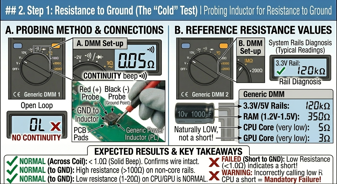
2. Step 1: Resistance to Ground (The “Cold” Test)
Before applying power, you must ensure there isn’t a dead short on the output of the stage.
- Set your multimeter to Resistance ($\Omega$) or Continuity.
- Place the Black probe on a screw hole (GND) and the Red probe on the Inductor (Coil).
- Reference Values:
- 3.3V / 5V Rails: Should be in the $k\Omega$ range.
- RAM Rail (1.2V - 1.5V): Usually $100\Omega$ to $500\Omega$.
- CPU / GPU Core Rails: Naturally very low ($1\Omega$ to $20\Omega$). Do not mistake this for a short.
3. Step 2: The “19V Rail” Cross-Check
A common failure is a shorted High-Side MOSFET. If this fails, 19V can leak directly into a 1V CPU, killing it instantly.
- Measure resistance between the Main 19V Rail (Current Sense Resistor) and the Inductor.
- Expected Reading: $OL$ (Open Loop) or several $M\Omega$.
- Failure Sign: $0\Omega$ to $10\Omega$. This indicates the High-Side MOSFET is shorted. Do not plug in the charger.
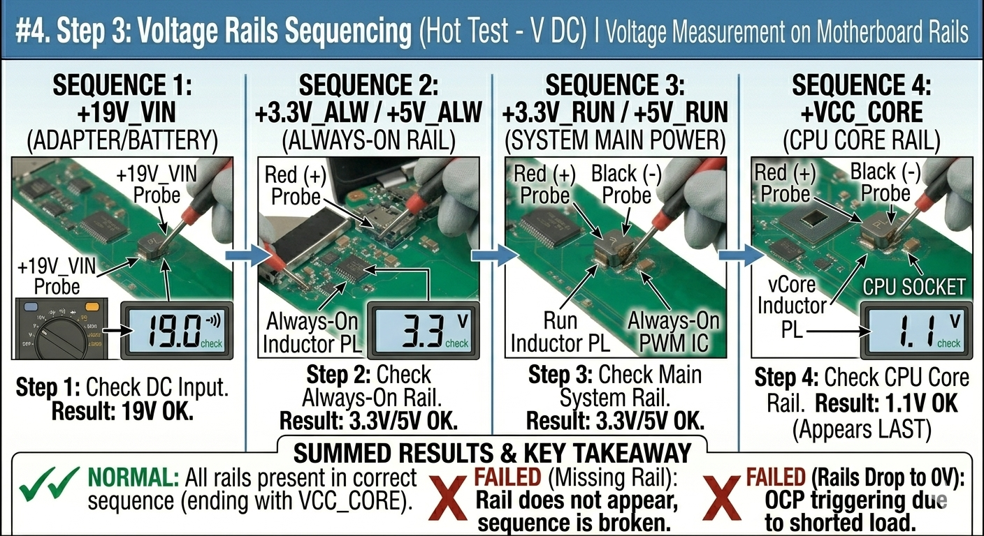
4. Step 3: Voltage Rails Sequencing (The “Hot” Test)
If there are no shorts, apply power and check for the presence of voltages in the correct order. Use DC Voltage Mode.
| Sequence | Rail Name | Purpose |
|---|---|---|
| 1 | +19V_VIN | Main power from adapter/battery. |
| 2 | +3.3V_ALW / +5V_ALW | “Always-on” power for the EC (Embedded Controller). |
| 3 | +3.3V_RUN / +5V_RUN | Main system power after pressing the power button. |
| 4 | +VCC_CORE | CPU Core voltage (appears last in the sequence). |
5. Step 4: Testing the PWM Enable (EN) Signal
If a power stage is receiving 19V but outputting 0V at the inductor, the PWM controller might not be “told” to turn on.
- Locate the PWM chip for the rail.
- Check the Enable (EN) pin and VCC pin of the IC using the schematic.
- Requirement: Most EN signals require 3.3V to start the chip. If this is 0V, the issue is further back in the power sequence (often the EC chip or PCH).
6. Summary of Failure Signs
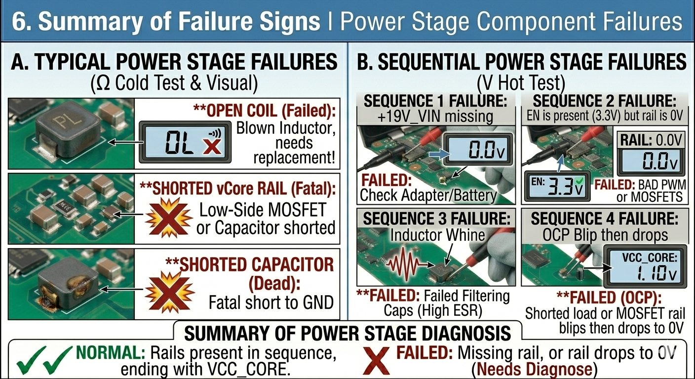
| Observation | Likely Culprit |
|---|---|
| 0V on Inductor, but EN is 3.3V | Failed PWM Controller or Bad MOSFETs. |
| Inductor Buzzing (Coil Whine) | Failed Filtering Capacitors (High ESR). |
| 19V on Inductor | Shorted High-Side MOSFET (Fatal for CPU/GPU). |
| Rail blips briefly to voltage then drops | Overcurrent Protection (OCP) due to a shorted load. |
7. Advanced: Oscilloscope Analysis
A multimeter only shows the average voltage. An oscilloscope is needed to see if the MOSFETs are “switching” correctly.
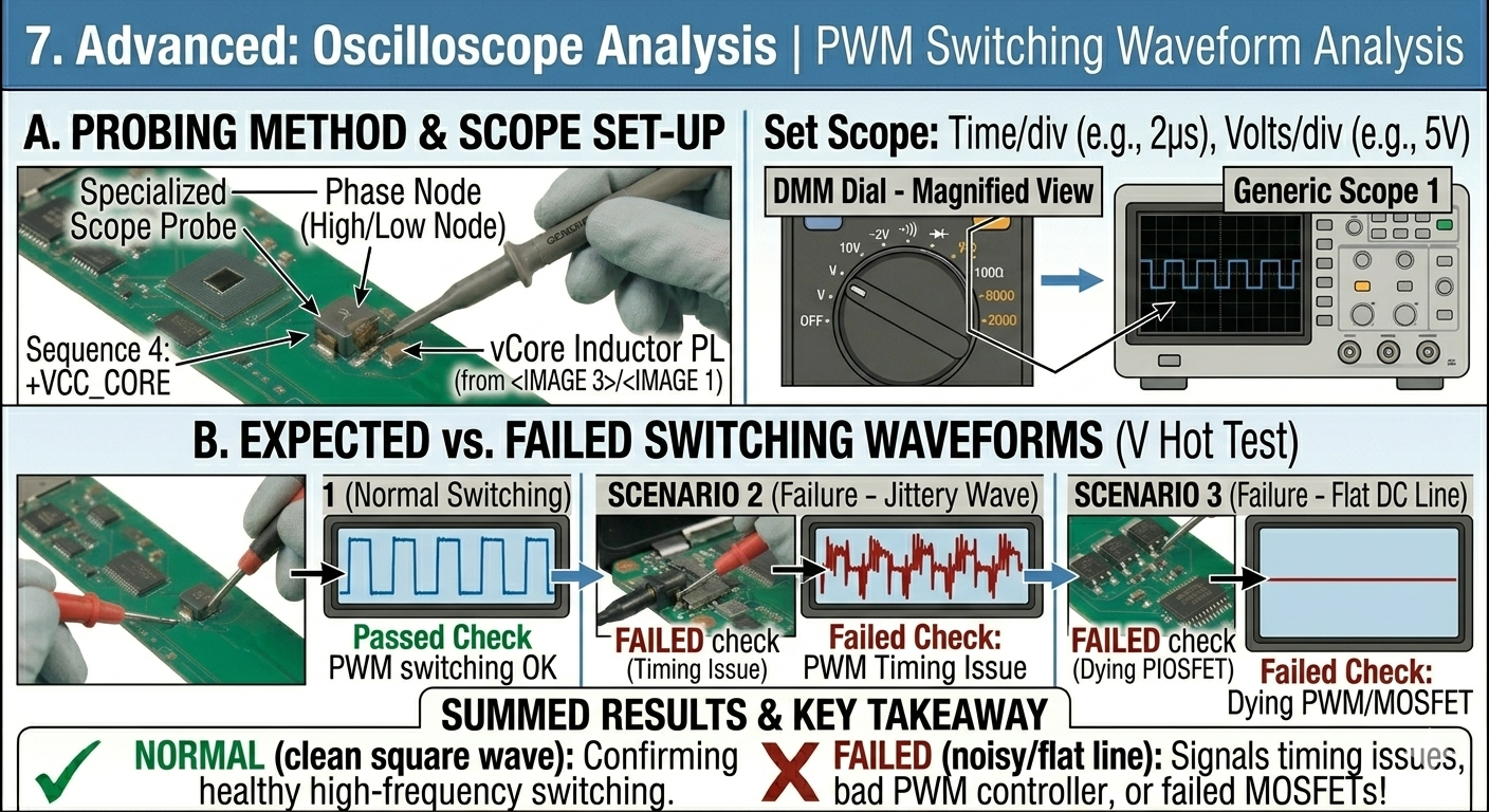
- Connect scope probe to the Phase Node (the junction between the MOSFETs and the inductor).
- Expected Reading: A clean square wave at roughly 300kHz to 1MHz.
- Failure Sign: A “jittery” wave or a flat DC line indicates a timing issue or a dying PWM controller.
8. Identifying Integrated Power Stages (DrMOS)
In modern high-end laptops, the MOSFETs and driver are combined into one chip (e.g., SIC632, AOZ5049).
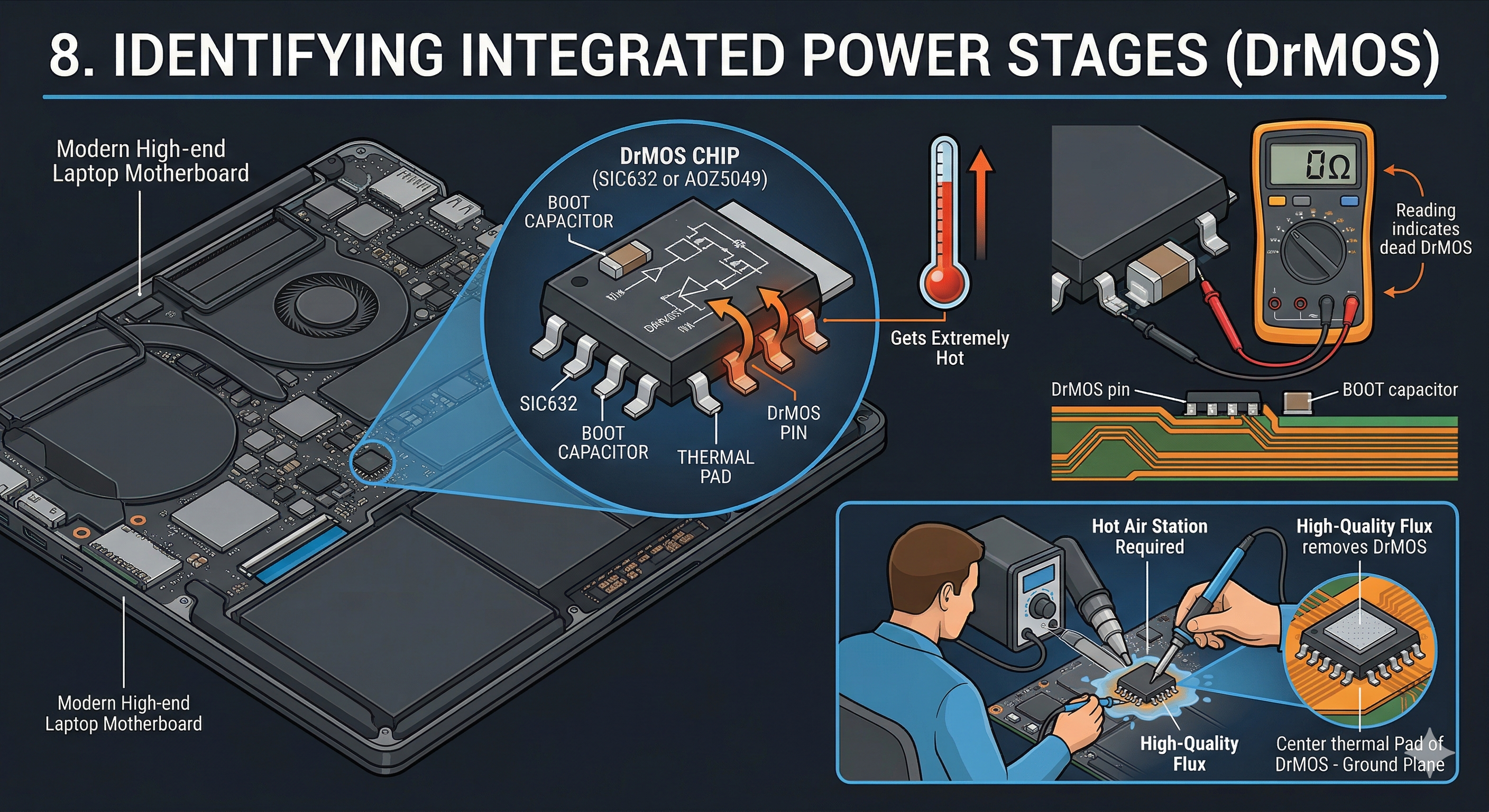
- Symptoms of failure: These chips often develop internal shorts and get extremely hot.
- Testing: Check the BOOT capacitor (usually a small capacitor very close to the chip). If this capacitor measures $0\Omega$, the DrMOS is usually dead.
- Replacement: These require a hot air station and high-quality flux, as the center thermal pad is soldered to the large ground plane.
9. Repair Precautions
- The “Safety” Rule: Never replace a MOSFET or PWM chip without also checking the current-sensing resistors and the gate resistors. A blown resistor will prevent the new chip from working.
- Discharge: Always remove the battery and the CMOS battery before soldering.
- Injecting Voltage: If you find a short on a low-voltage rail (like CPU), never inject more than 1V. Higher voltage will destroy the silicon of the processor instantly.
Integrated Power Stage (DrMOS) Identification Guide
10. Part Number Lookups
Integrated chips use microscopic markings. Use a microscope to identify the top-side code.
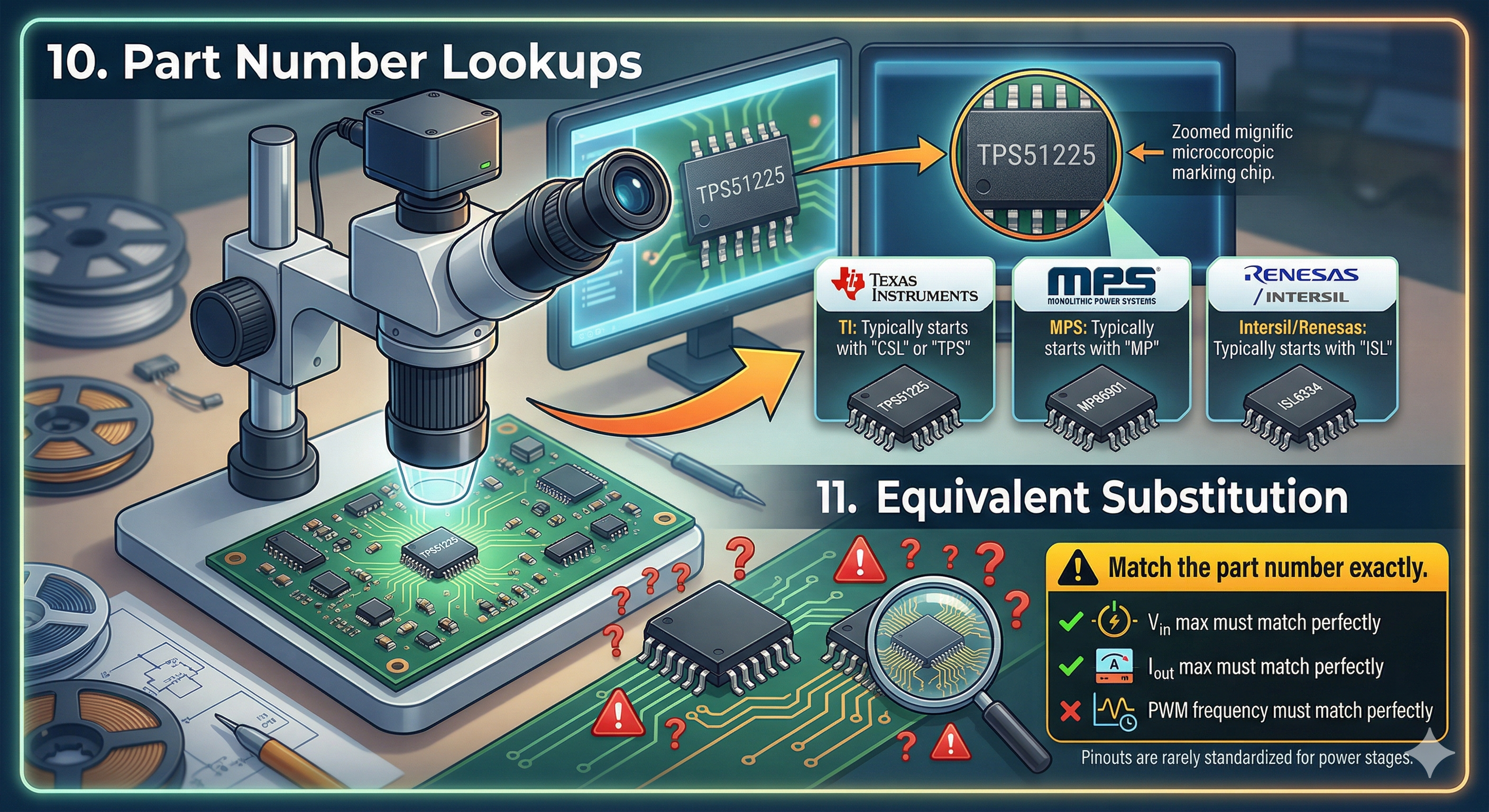
- TI (Texas Instruments): Usually starts with “CSL” or “TPS”.
- MPS (Monolithic Power Systems): Usually starts with “MP”.
- Intersil/Renesas: Usually starts with “ISL”.
11. Equivalent Substitution
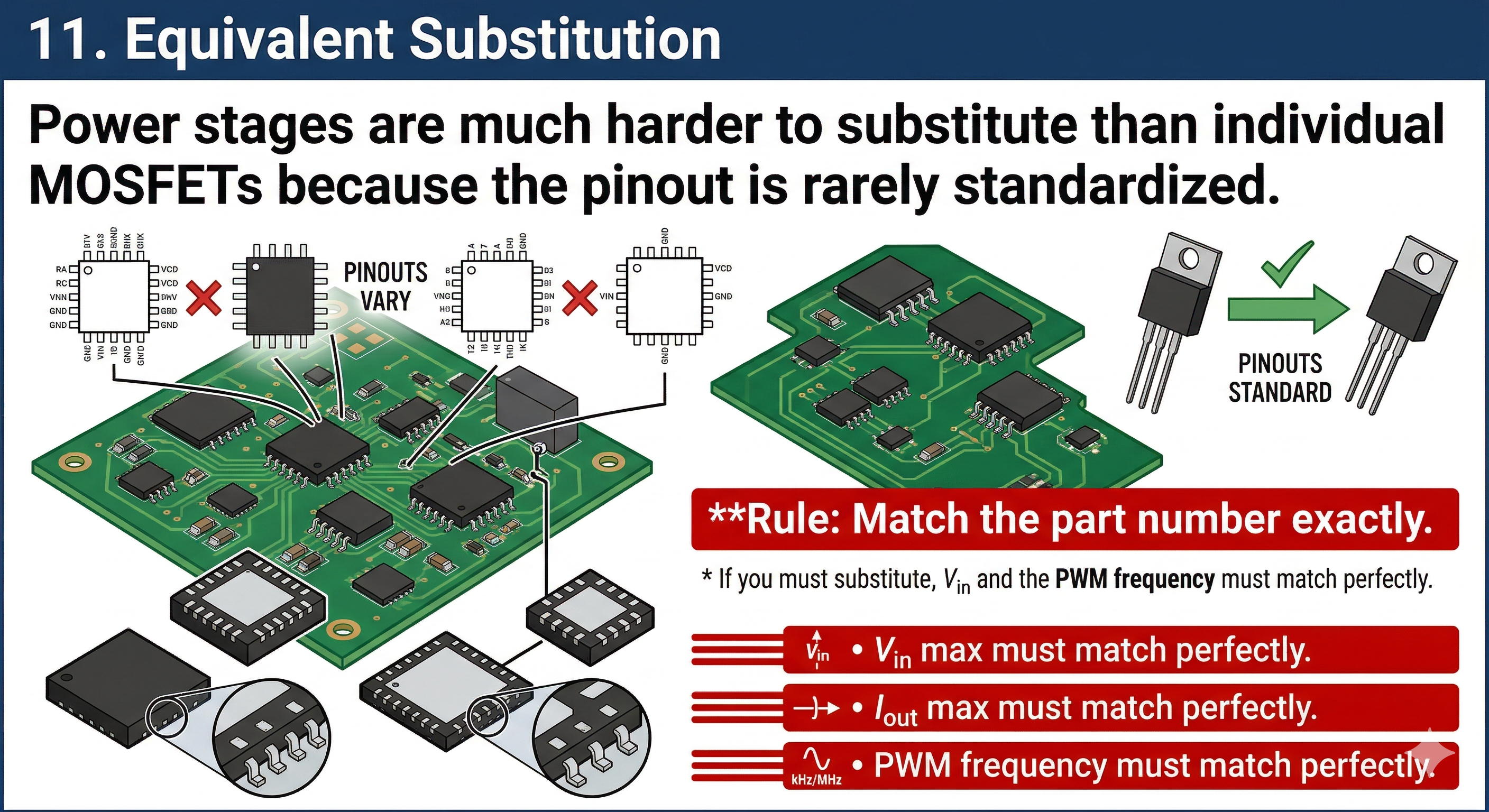 Power stages are much harder to substitute than individual MOSFETs because the pinout is rarely standardized.
- Rule: Match the part number exactly. * If you must substitute, $V_{in}$ max, $I_{out}$ max, and the PWM frequency must match perfectly.
12. Search Resources
- BadCaps.net / Vinfix: Best forums for laptop schematics and boardviews.
- LogiWiki: Detailed guides on power rail sequencing for MacBooks and PCs.
- S-Manuals: Massive database for SMD code identification.