Capacitor Testing
Capacitor Diagnostic and Testing Guide
This document provides a technical walkthrough for testing capacitors, ranging from large electrolytic filter caps to tiny ceramic decoupling capacitors found on laptop motherboards and general PCBs.
1. Capacitor Types and Identification
Before testing, identify the type of capacitor, as their failure modes and testing priorities differ significantly.
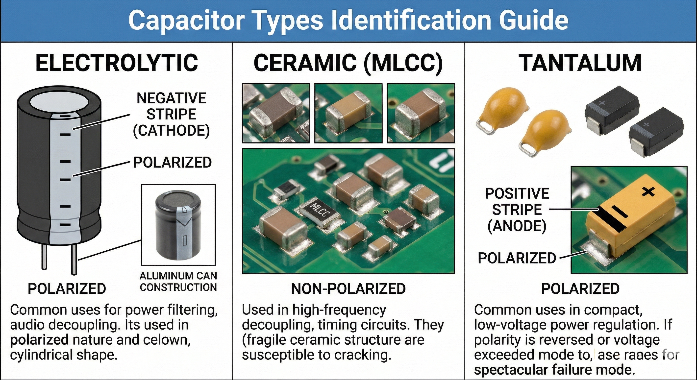
- Electrolytic: Cylindrical, polarized (has a negative stripe), prone to drying out, bulging, or leaking electrolyte.
- Ceramic (MLCC): Tiny, beige or brown rectangles, non-polarized, prone to internal cracking and “hard shorts.”
- Tantalum: Rectangular, molded plastic (usually yellow or black), polarized (marked with a stripe on the positive side), prone to spectacular fire-like shorts if polarity is reversed or voltage rating exceeded.
2. Preliminary Step: Discharge the Capacitor
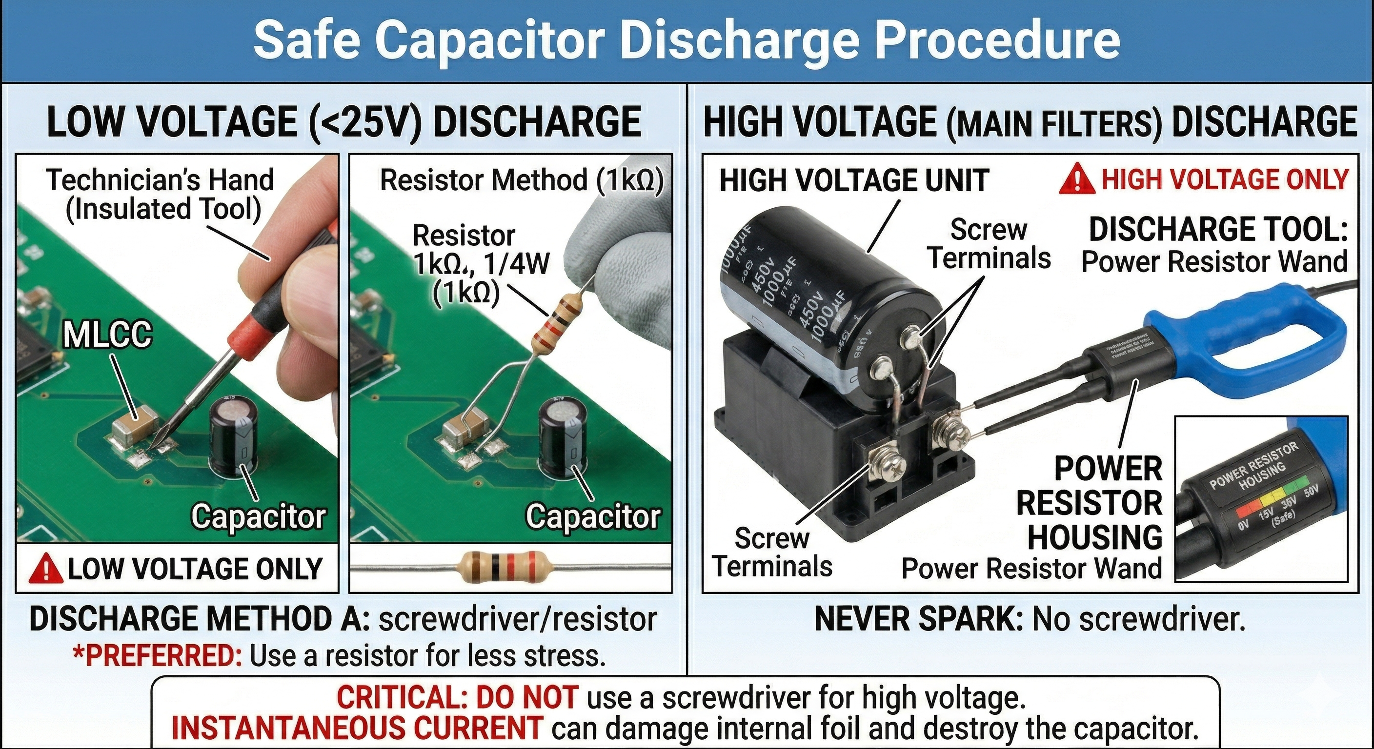
CRITICAL: Capacitors store energy. Testing a charged capacitor can destroy your multimeter, give you a painful shock, or even cause an explosion in high-power applications.
- Low Voltage (<25V): Short the terminals together with a screwdriver or a discharge resistor (1k$\Omega$).
- High Voltage (Main Filters): Always use a designated discharge tool (a power resistor on probes). Never “spark” a high-voltage cap with a screwdriver, as the instantaneous current can damage the internal foil and destroy the capacitor.
3. Resistance and Continuity Testing (The “Short” Check)
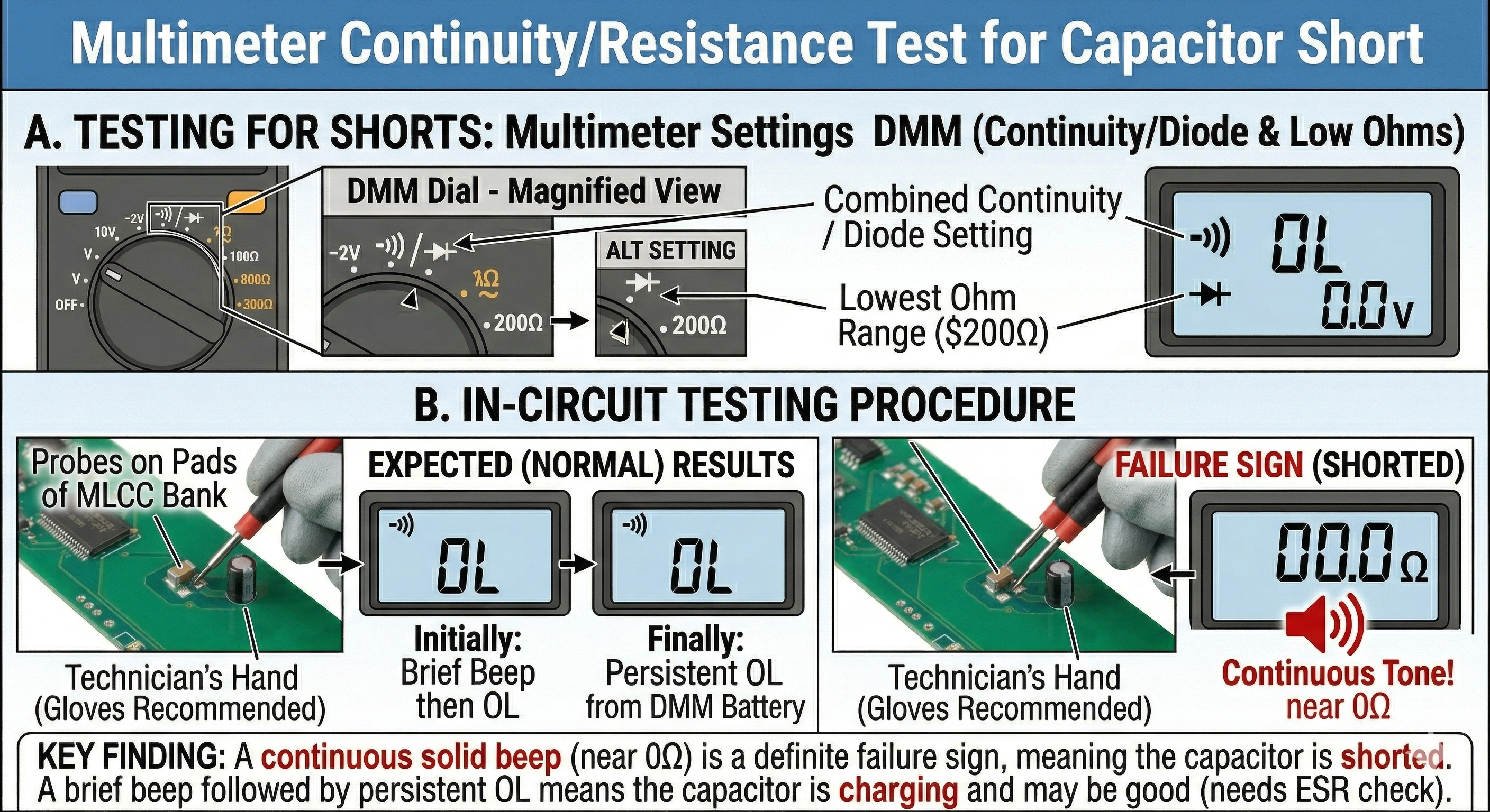
This is the fastest way to diagnose a failed capacitor in-circuit. Set your multimeter to Continuity/Diode Mode or the lowest Ohm ($\Omega$) setting.
A. Testing for Shorts
- Place the probes on both terminals of the capacitor.
- Expected Result (Multimeter Beeps initially): You might hear a brief “beep” that quickly stops. This is the multimeter’s battery charging the capacitor.
- Expected Result (No Beep): The continuity should remain OL (Open Loop).
- Failure Sign: A continuous, solid beep (near 0$\Omega$ resistance) indicates the capacitor is shorted.
B. Resistance “Rise” Test
This test gives a basic go/no-go indication by watching the capacitance charging.
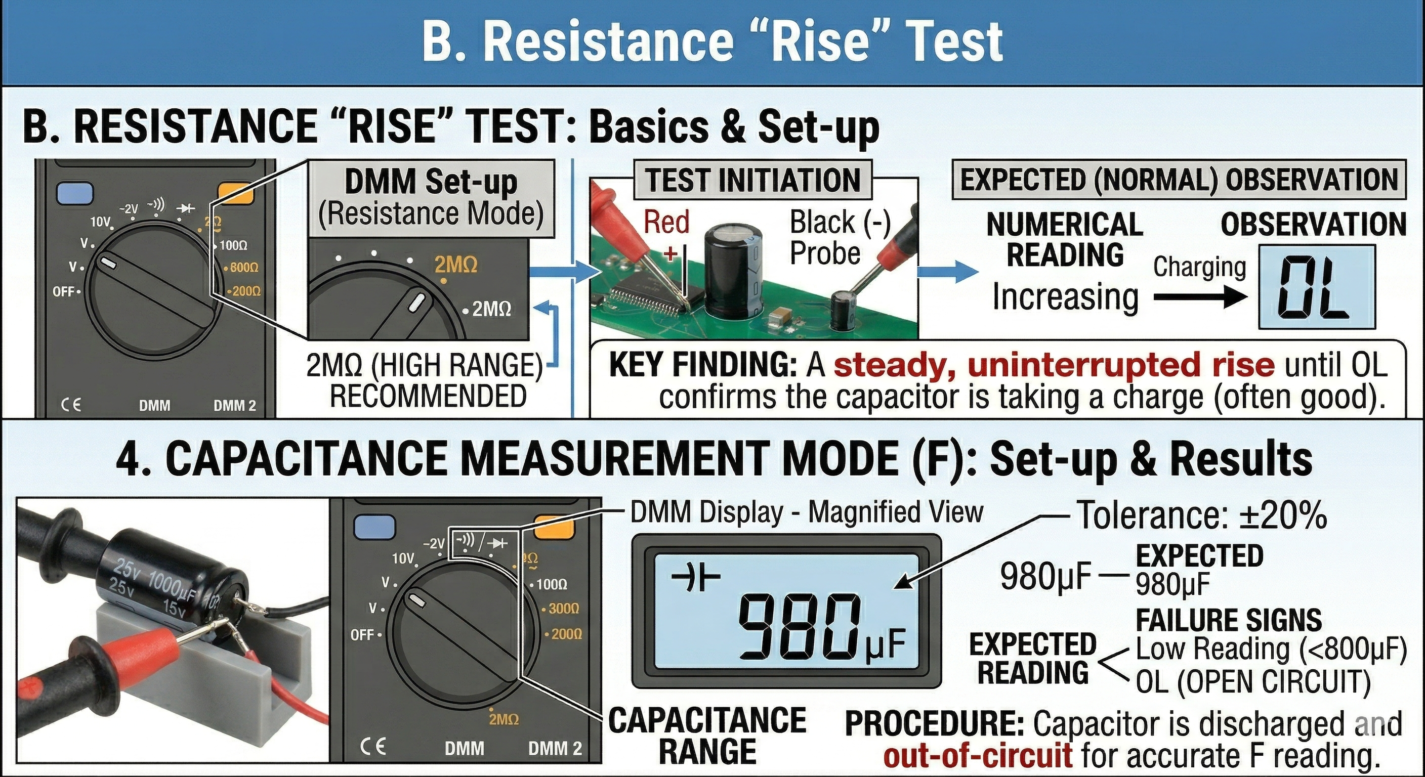
- Set the DMM to a high resistance range ($200k\Omega$ or $2M\Omega$).
- Place the probes across the capacitor.
- Expected Observation: The numerical reading should start low and steadily increase until it reaches OL, indicating the capacitor has fully charged from the multimeter’s internal power supply.
4. Capacitance Measurement Mode ($F$)
Most modern digital multimeters include a dedicated capacitance setting marked with the capacitor symbol ($\dashv \vdash$).
- Discharge the capacitor completely (Step 2).
- Remove the capacitor from the circuit (out-of-circuit is necessary for an accurate capacity reading).
- Connect the probes to the terminals (polarity doesn’t strictly matter for capacity measurement, but the meter may show a ‘-‘ sign if reversed).
- Expected Reading: The measurement should be within the tolerance specified on the casing (usually $\pm 20\%$).
- Failure Sign: A reading significantly lower than the stated value indicates an aged/failed capacitor. A reading of “OL” or no change suggests the capacitor is open-circuit.
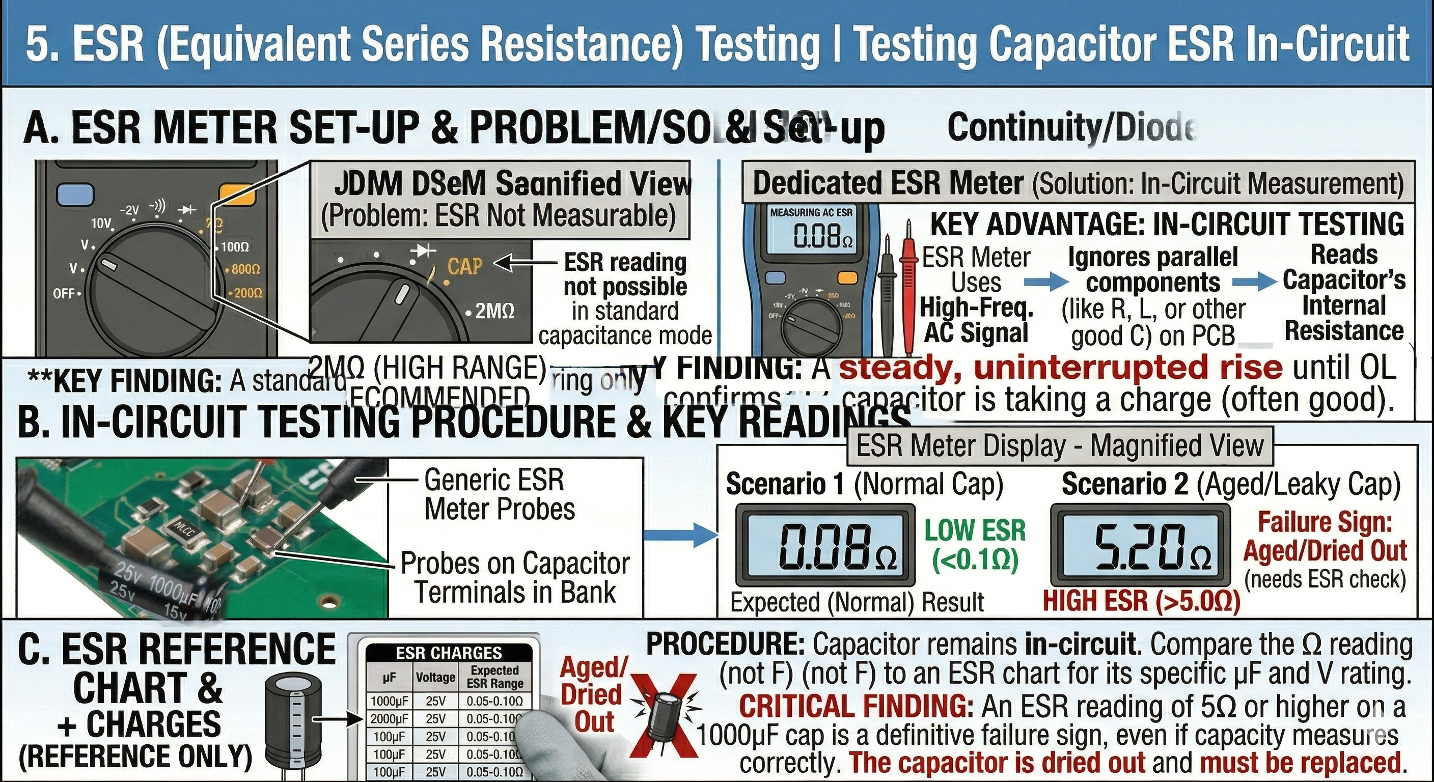
5. ESR (Equivalent Series Resistance) Testing
ESR is the single most critical measurement for diagnosing performance issues, especially in switching power supplies (PSUs) and logic boards (ESR determines filtering effectiveness). As capacitors age, their ESR rises, causing voltage ripple and circuit failure, even if the total capacity looks correct.
- The Problem: A standard multimeter measuring capacity cannot measure ESR.
- The Solution: Use an ESR Meter.
Key Advantages of ESR Meters:
- In-Circuit Testing: Most dedicated ESR meters can measure ESR without removing the capacitor from the PCB, as they use high-frequency AC signals that are unaffected by surrounding parallel components.
- Accuracy: ESR provides a definitive health check where simple capacitance measurement fails.
Interpretation:
Compare your measured ESR reading (in Ohms) to an ESR reference chart, often printed on the meter itself. A good electrolytic capacitor (e.g., $1000\mu F$, 25V) should have very low ESR, typically $<0.1\Omega$. If it reads $5\Omega$ or higher, it is “dried out” and must be replaced.
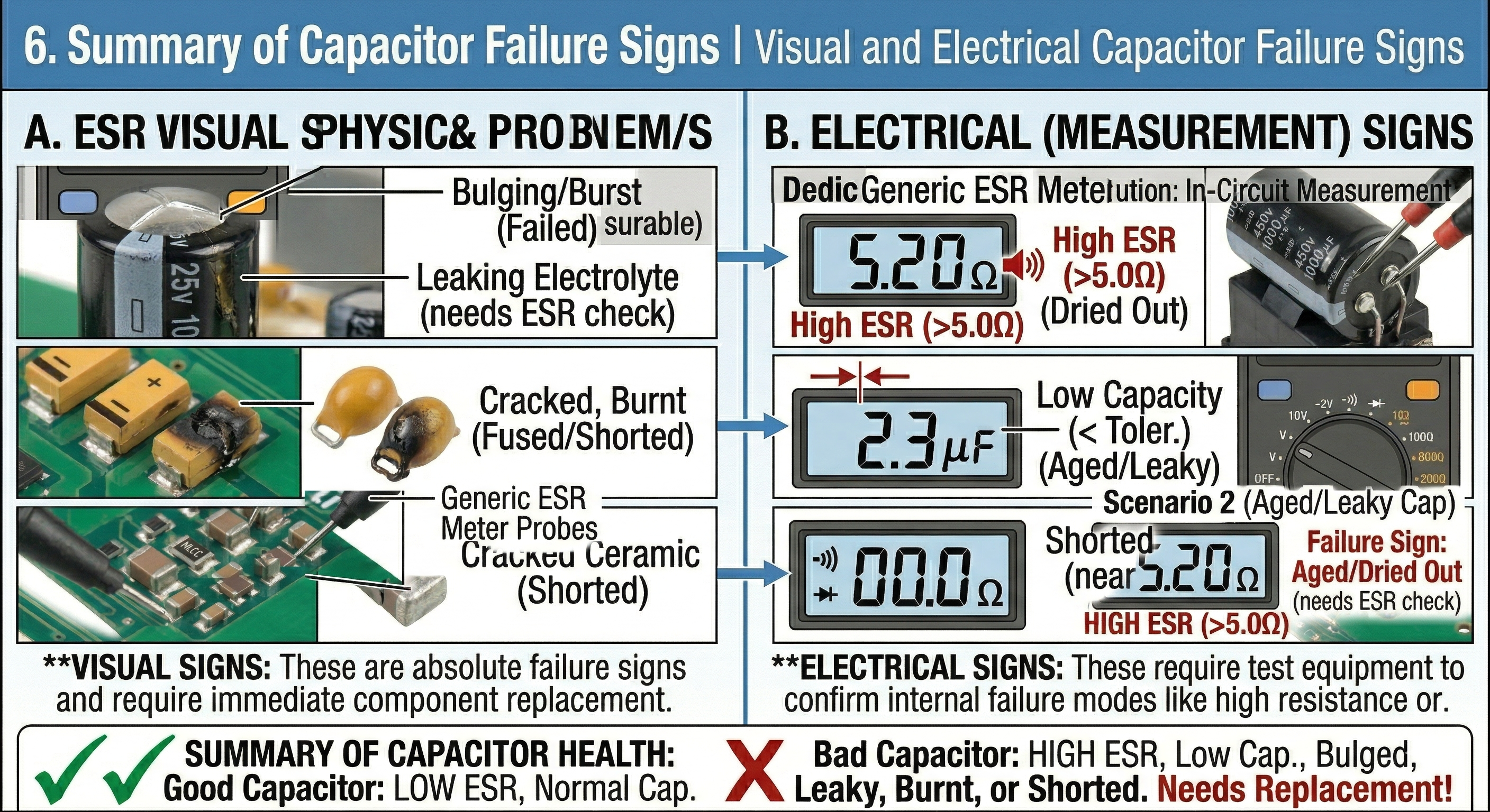
6. Summary of Capacitor Failure Signs
| Observation | Diagnosis |
|---|---|
| Beep/0$\Omega$ reading | Shorted (Failed) |
| Reading “OL” in Capacitance Mode | Open Circuit (Internal connection broken) |
| Low Capacity reading | Aged/Dried Out (Failed) |
| High ESR reading | Aged (Poor performance/Failure) |
| Visual Bulging, Leaking, or Burnt PCB | Failed (Replace immediately) |
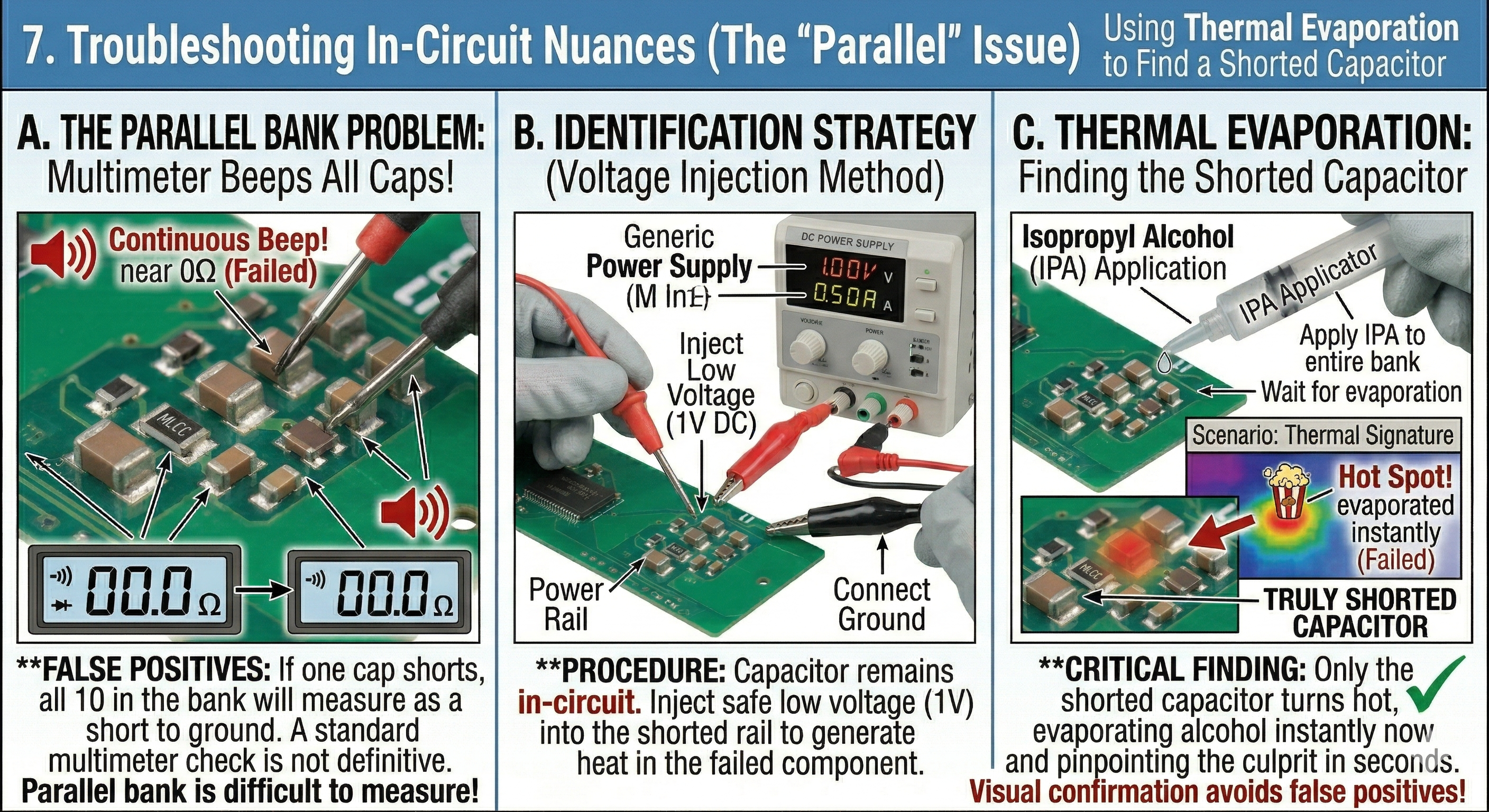
7. Troubleshooting In-Circuit Nuances (The “Parallel” Issue)
Diagnostics on densely populated PCBs, like laptop motherboards, are complicated by parallel circuit paths.
- The Parallel Bank Problem: Capacitors (especially MLCCs) are frequently arranged in “banks” or parallel decoupling arrays (e.g., 10 identical caps on a CPU power rail).
- False Postives: If one capacitor in that bank shorts, all caps in the bank will measure as a short to ground.
- Identification Strategy (Voltage Injection):
- Inject a safe, low voltage (e.g., 1V) into the shorted rail using a DC power supply.
- Apply Isopropyl Alcohol (IPA) to the capacitor bank.
- Observe: The alcohol will evaporate instantly off the truly shorted capacitor as it generates heat, pinpointing the failed component in seconds.
Capacitor Replacement and Substitution Guide
When a capacitor is confirmed dead, finding a suitable replacement is straightforward but requires strict attention to ratings.
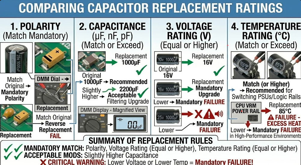
8. Matching Key Parameters
You can substitute a replacement capacitor by comparing four critical specifications.
1. Polarity
Ensure the replacement matches the polarity requirement:
- Electrolytic: Align the negative stripe.
- Tantalum: Align the positive marking stripe.
- Ceramic: Either orientation is fine.
2. Capacitance ($\mu F, nF, pF$)
- Rule: Match the original value.
- Acceptable Deviation: For non-critical applications (like large power filter banks), using a higher capacitance value is generally acceptable (e.g., 680$\mu F$ instead of 470$\mu F$), but never use a lower value.
3. Voltage Rating ($V$)
This is the maximum continuous working voltage.
- Rule: The replacement voltage rating must be Equal or Higher.
- Example: Replacing a 10V capacitor with a 25V capacitor is safe (often an upgrade). Replacing a 10V capacitor with a 6.3V capacitor will result in failure when power is applied.
4. Temperature Rating ($^{\circ}C$)
Always match or exceed the temperature rating. This is crucial in switching power supplies and high-heat areas near CPUs. Look for $105^{\circ}C$ rated capacitors for reliability; avoid substituting $85^{\circ}C$ caps in high-performance or high-heat environments.
Pro Tip: Ceramic MLCCs fail as dead shorts on power rails. When this happens on high-voltage rails (e.g., 19V DC input), the surge often chars the PCB. Before soldering the new MLCC, you must meticulously scrape away the carbonized (burnt) PCB material between the pads, as carbon is conductive and will create a new short circuit.