Inductor Diagnostics
Inductor and Coil Diagnostic Guide
This document provides a technical walkthrough for testing inductors (coils) commonly used in power delivery stages, VRMs, and filtering circuits on laptop motherboards and general electronics.
1. Inductor Overview and Function
In laptop circuits, inductors (often labeled as PL or L) work alongside MOSFETs and capacitors to smooth out voltage ripples and store energy in a magnetic field. Unlike resistors, a healthy inductor should have nearly zero resistance to DC current.
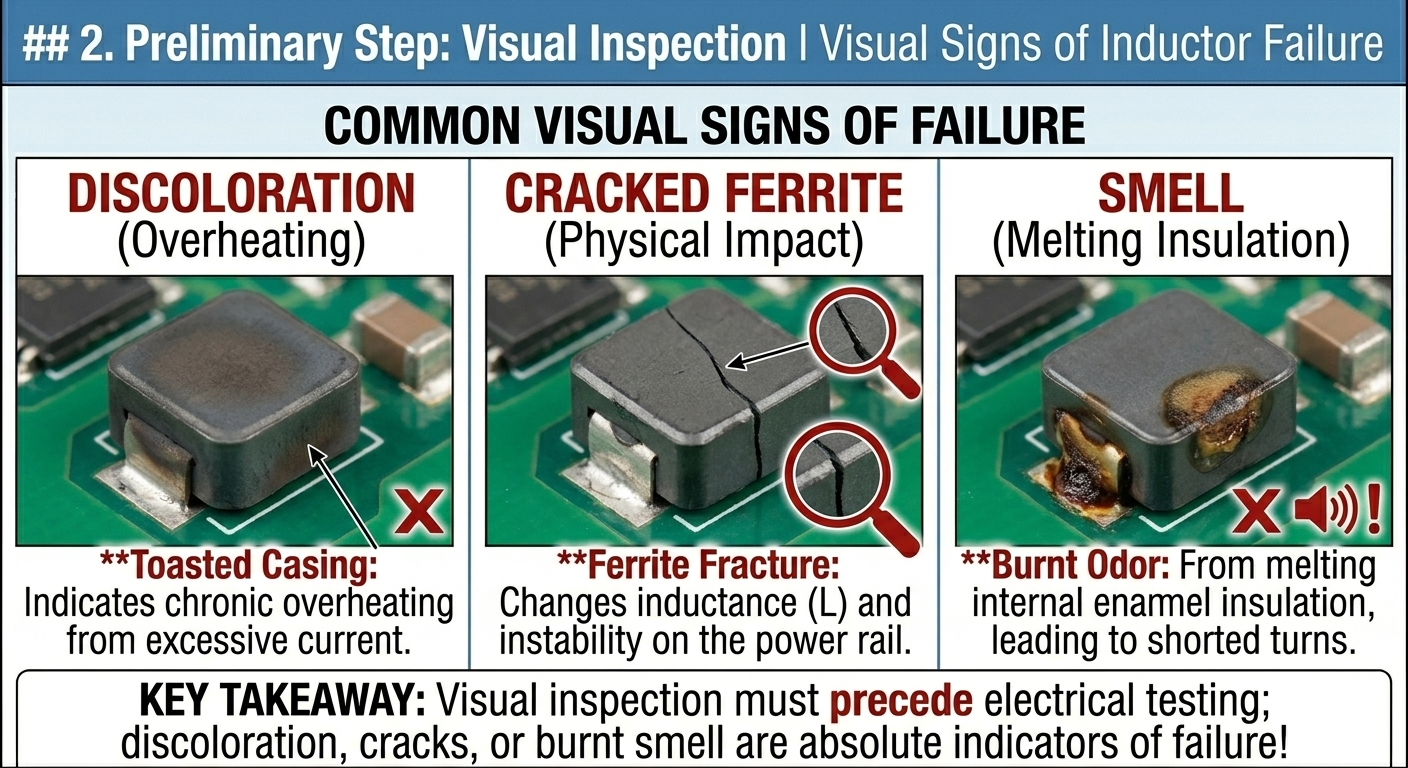
2. Preliminary Step: Visual Inspection
Inductors are physically robust but can fail due to extreme heat, excessive current, or physical impact.
- Discoloration: A “toasted” or darkened look on the coil casing indicates chronic overheating.
- Cracked Ferrite: Modern molded inductors can crack. Even a hairline fracture in the ferrite core can change the inductance value ($L$), causing instability in the power rail.
- Smell: A pungent, “burnt sugar” or metallic smell usually indicates the enamel insulation on the internal copper wire has melted, leading to internal shorts.
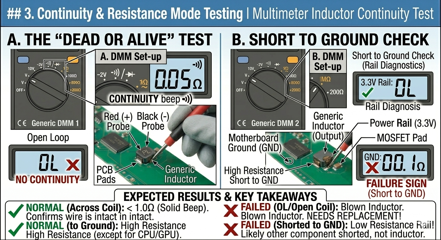
3. Continuity and Resistance Mode Testing
Since an inductor is essentially a wound piece of insulated wire, its primary characteristic is continuity.
A. The “Dead or Alive” Test
Set your multimeter to Continuity Mode (Beep) or the lowest Ohm ($\Omega$) setting.
- Place probes on both sides of the inductor.
- Expected Reading: A solid beep and a resistance of $0.01\Omega$ to $0.5\Omega$.
- Failure Sign: If the meter shows OL (Open Loop), the inductor is “blown” (the internal wire has snapped or melted).
B. Short to Ground Check
Inductors are often part of a specific voltage rail (e.g., 3.3V, 5V, CPU_CORE).
- Place one probe on the inductor and the other on a known GND (Ground) point.
- Expected Reading: High resistance (except on CPU/GPU rails where $1\Omega$–$10\Omega$ is normal).
- Failure Sign: A $0\Omega$ reading to ground usually indicates a shorted decoupling capacitor or high-side MOSFET, not necessarily the inductor itself.
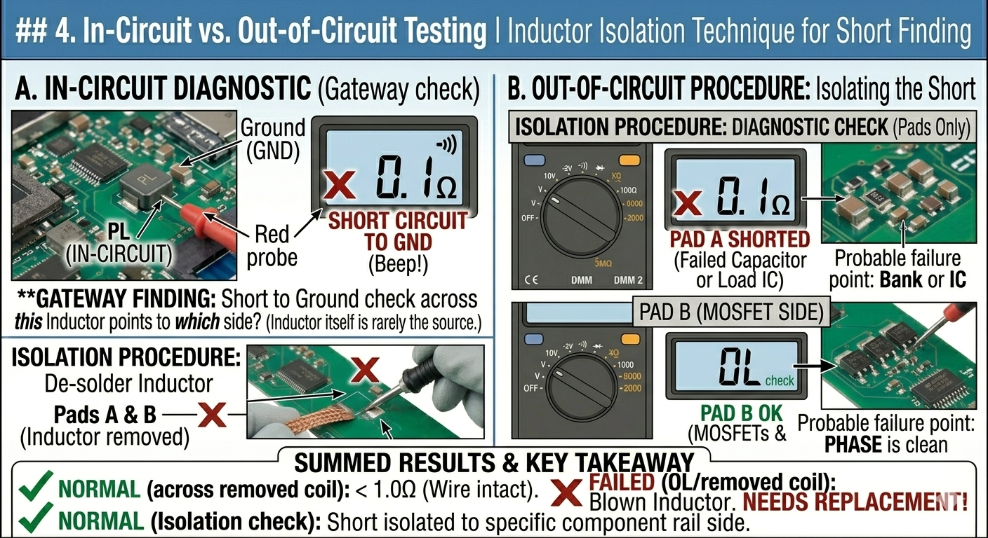
4. In-Circuit vs. Out-of-Circuit Testing
Inductors almost never fail “shorted” to ground by themselves. However, they are perfect “gateways” for diagnostics.
- The “Isolation” Trick: If you have a short circuit on a power rail, removing the inductor is the best way to determine which side of the circuit the short is on.
- Procedure: De-solder the inductor. Check resistance to ground on both pads.
- If Pad A (System/Output side) is shorted, the problem is a capacitor or the Load IC.
- If Pad B (Phase/MOSFET side) is shorted, the MOSFETs or the PWM controller are dead.
5. Summary of Inductor Failure Signs
| Observation | Likely Status | | :— | :— | | Beep / Near $0\Omega$ across the coil | Healthy (Wire is intact) | | OL (Open Loop) across the coil | Failed (Open circuit/Blown) | | Cracked or “Leaking” casing | Failed (Core damage/Saturation) | | Buzzing/Whining noise (Coil Whine) | Vibrating (Electrically okay, but physically loose) |
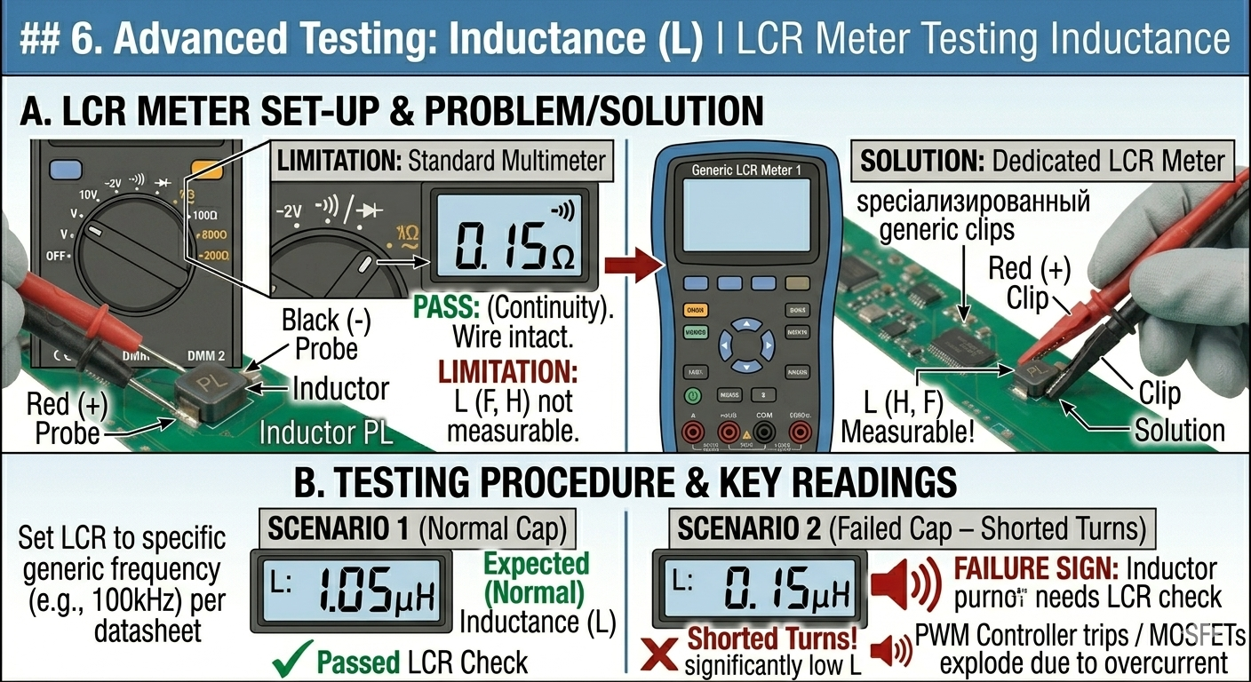
6. Advanced Testing: Inductance ($L$)
Standard multimeters cannot measure inductance. You need an LCR Meter to verify the Henry ($H$) rating.
- Test: Set LCR meter to the frequency specified in the datasheet (usually 100kHz).
- Significance: An inductor might show continuity but have “shorted turns” (internal layers touching). This drops the inductance significantly, causing the PWM controller to trip or the MOSFETs to explode due to overcurrent.
Inductor Identification and Replacement
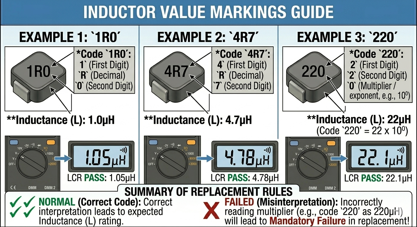
7. Identifying the Value
Inductor values are typically printed on the top in a three-digit code:
- R: Acts as a decimal point.
- Example 1:
1R0= $1.0\mu H$ - Example 2:
4R7= $4.7\mu H$ - Example 3:
220= $22\mu H$
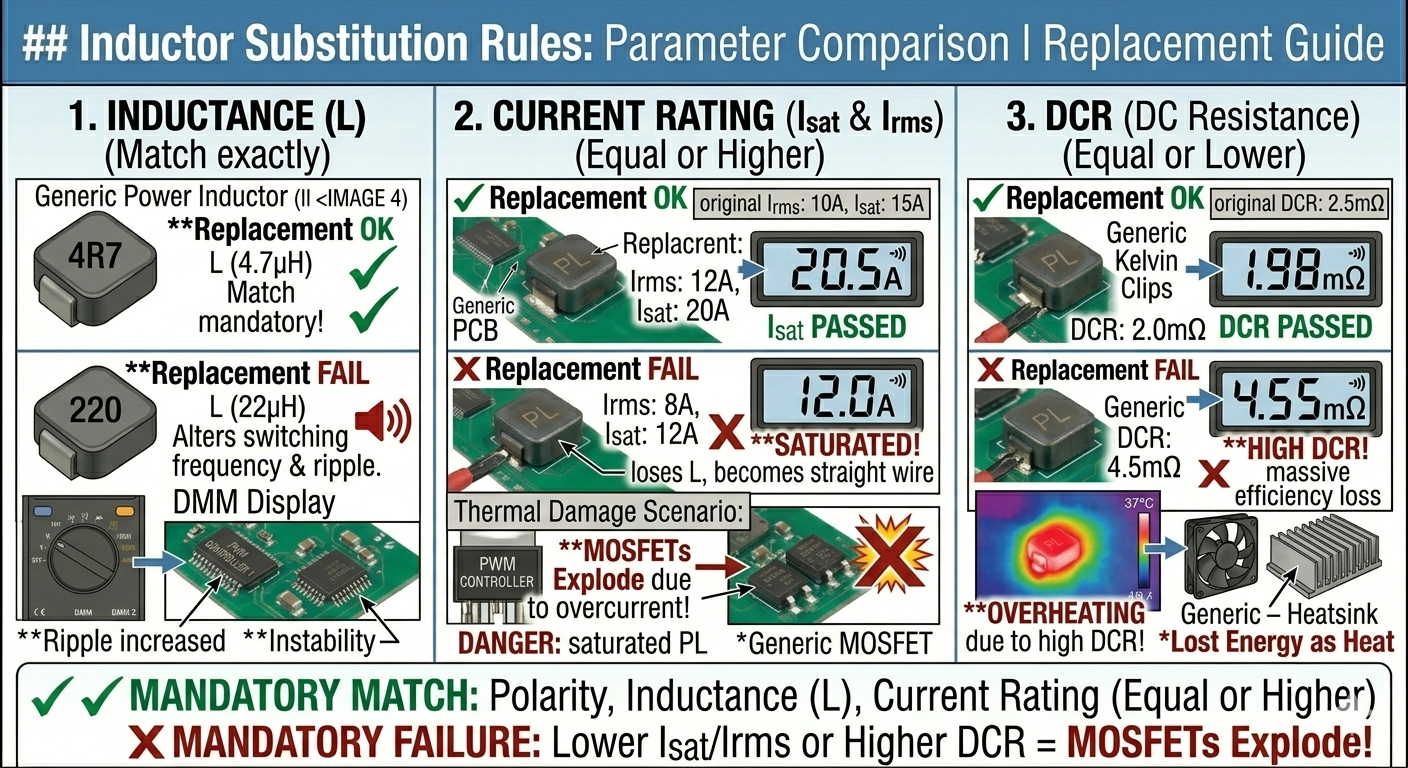
8. Substitution Rules
If you must replace an inductor and cannot find an exact match, follow these rules:
1. Inductance ($L$)
- Rule: Match exactly whenever possible.
- Note: Changing the inductance alters the switching frequency and ripple. A lower value might cause more noise; a higher value might slow down transient response.
2. Current Rating ($I_{sat}$ and $I_{rms}$)
- Rule: The replacement must have an Equal or Higher current rating.
- Danger: If you use an inductor with a lower current rating, it will saturate, lose its inductance, and essentially become a straight wire, likely killing the MOSFETs instantly.
3. DCR (DC Resistance)
- Rule: The replacement must have an Equal or Lower DCR.
- Reason: Higher DCR means more energy is lost as heat.
9. The “Coil Whine” Phenomenon
If a motherboard is “screaming” or making a high-pitched noise:
- It is usually an inductor vibrating at a high frequency because the internal winding is loose.
- This is often caused by a failing filtering capacitor elsewhere, forcing the inductor to handle excessive ripple current.
- Fix: Check the ESR of capacitors on that rail before replacing the noisy inductor.