Mosfet Diagnostics
MOSFET Diagnostic and Testing Guide
This document provides a technical walkthrough for testing Metal-Oxide-Semiconductor Field-Effect Transistors (MOSFETs) commonly found in laptop motherboards and general electronics.
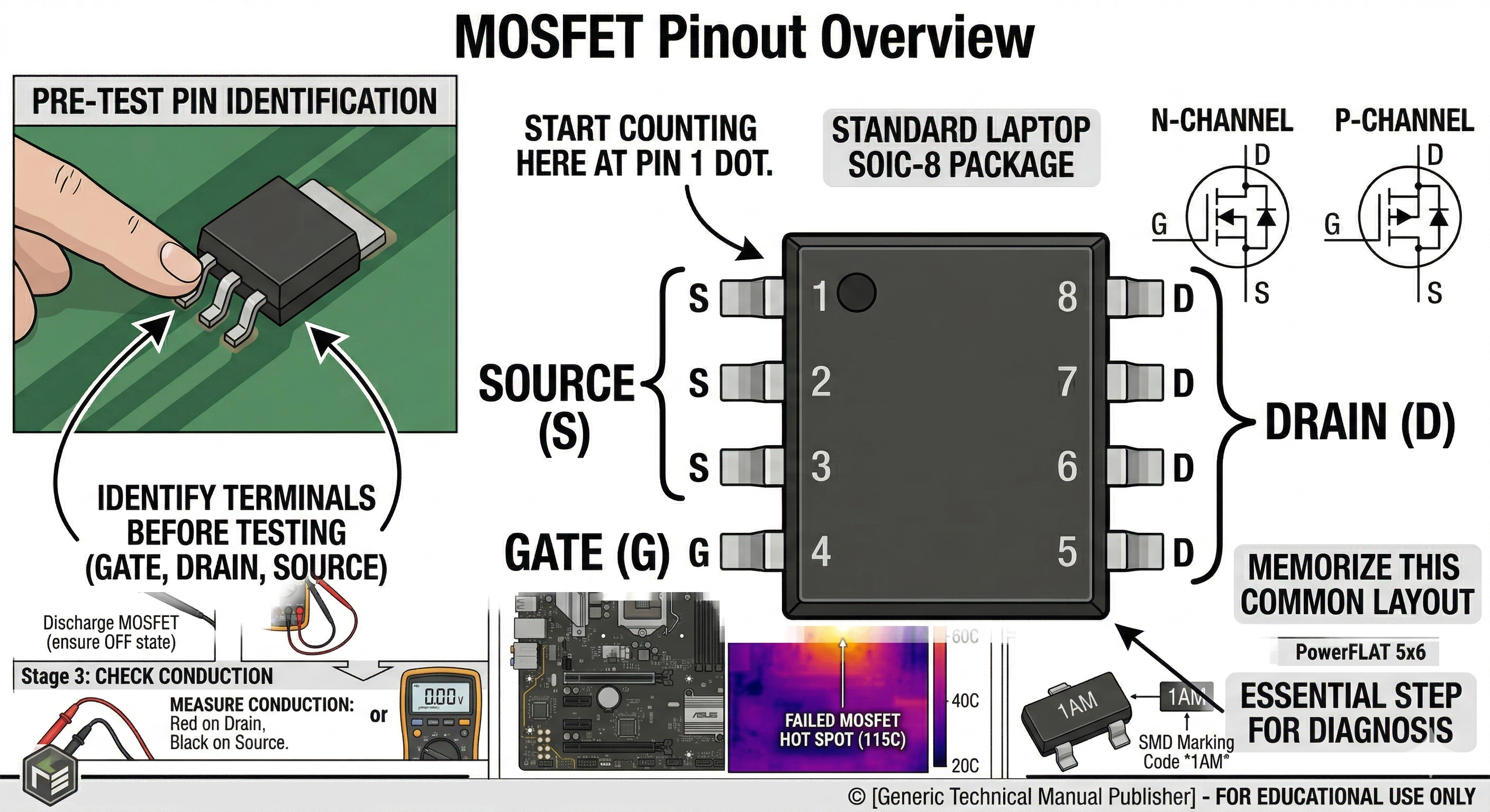
1. MOSFET Pinout Overview
Before testing, identify the three terminals: Gate (G), Drain (D), and Source (S). In most laptop SOIC-8 packages, pins 1-3 are Source, pin 4 is Gate, and pins 5-8 are Drain.
2. Preliminary Step: Discharge the MOSFET
Before using a multimeter, short all pins together using a screwdriver or your finger to discharge any internal capacitance. This ensures the MOSFET starts in a “closed” state.
3. Diode Mode Testing
The most common way to test a MOSFET is using the Diode Mode on a digital multimeter.
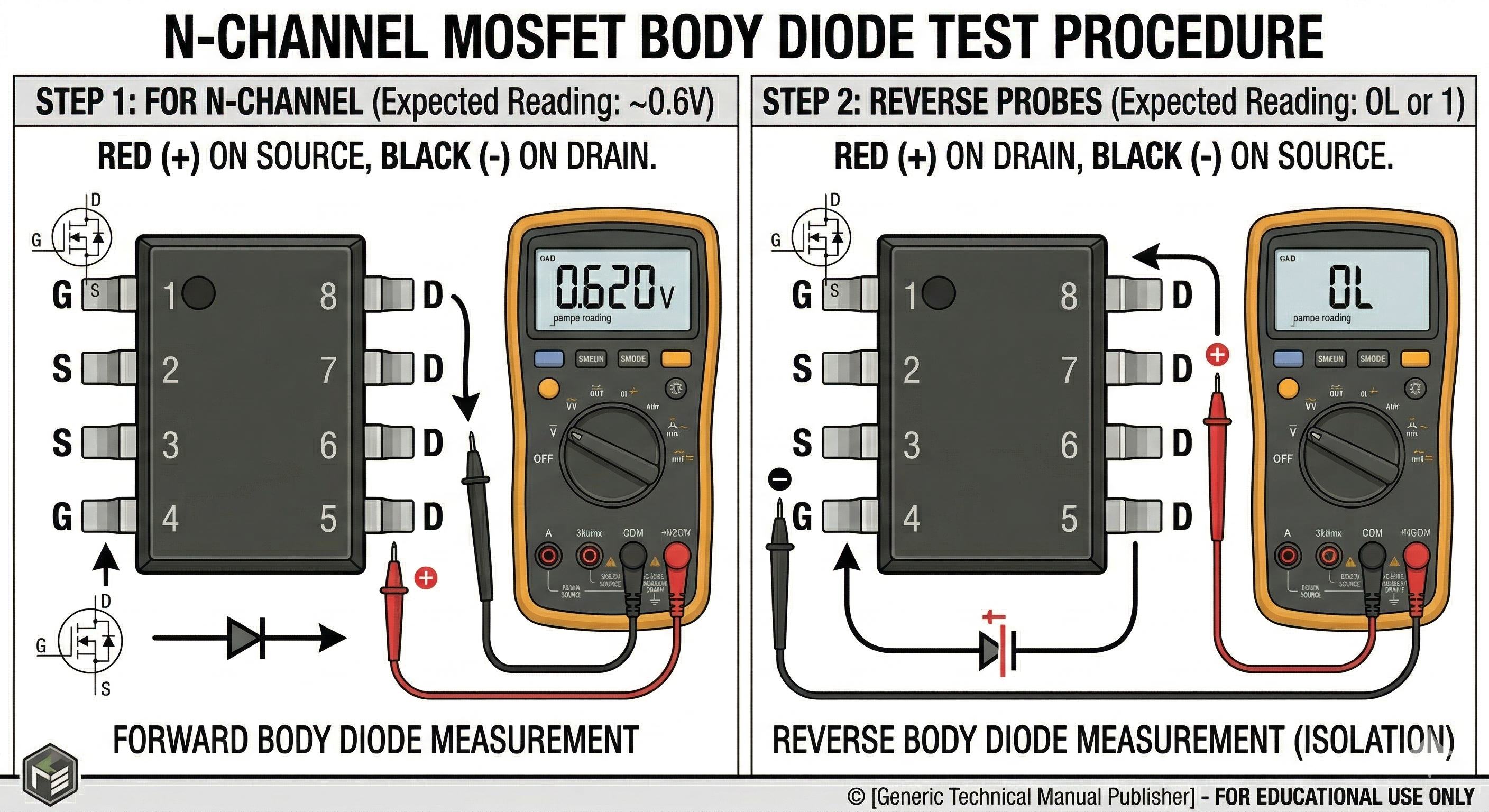
A. Testing the Internal Body Diode
A functional MOSFET has an internal diode between the Source and Drain.
- For N-Channel: Place the Red (+) probe on the Source and the Black (-) probe on the Drain.
- Expected Reading: 0.4V to 0.9V (Diode drop).
- Reverse the Probes: Place Red on Drain and Black on Source.
- Expected Reading: OL (Open Loop) or “1”.
B. Testing for Gate Isolation
The Gate must be isolated from both the Drain and the Source.
- Place one probe on the Gate and the other on the Drain, then the Source.
- Expected Reading: OL (Open Loop) in both directions. If you see a voltage drop or a low resistance, the Gate is leaked/blown.
4. Resistance Mode (Short Circuit Test)
Set your multimeter to the lowest Ohm ($\Omega$) setting or Continuity mode.
- Drain to Source: Should show very high resistance (Megaohms) if the MOSFET is off. If it beeps or shows near 0$\Omega$, the MOSFET is shorted.
- Gate to Source/Drain: Should always be high resistance. Any low reading indicates a failed component.
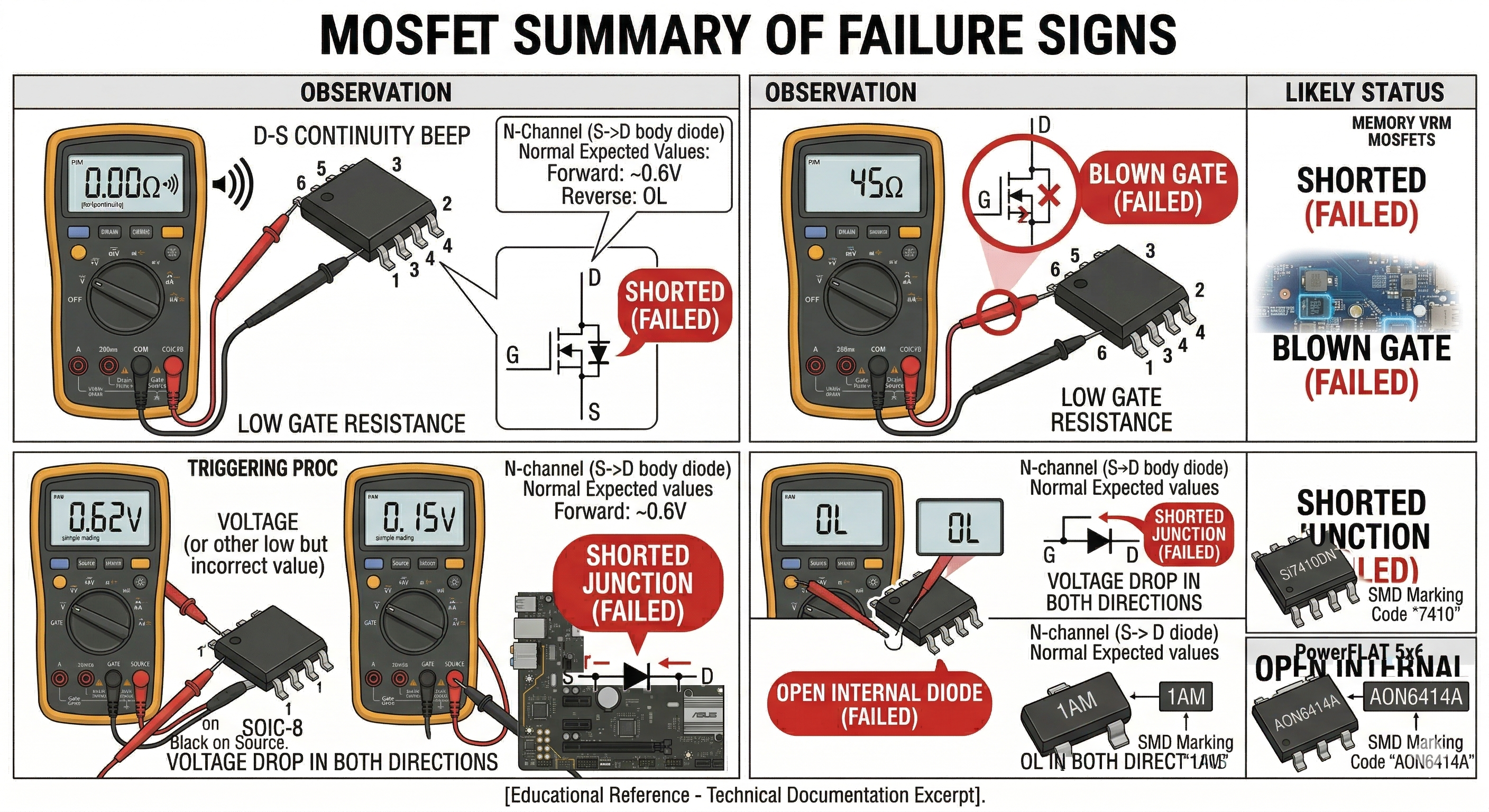
5. Summary of Failure Signs
 | Observation | Likely Status |
| :— | :— |
| Beep/0Ω between Drain and Source | Shorted (Failed) |
| Low resistance between Gate and any other pin | Blown Gate (Failed) |
| Voltage drop in both directions (D-S and S-D) | Shorted Junction (Failed) |
| OL in both directions (D-S and S-D) | Open Internal Diode (Failed) |
| Observation | Likely Status |
| :— | :— |
| Beep/0Ω between Drain and Source | Shorted (Failed) |
| Low resistance between Gate and any other pin | Blown Gate (Failed) |
| Voltage drop in both directions (D-S and S-D) | Shorted Junction (Failed) |
| OL in both directions (D-S and S-D) | Open Internal Diode (Failed) |

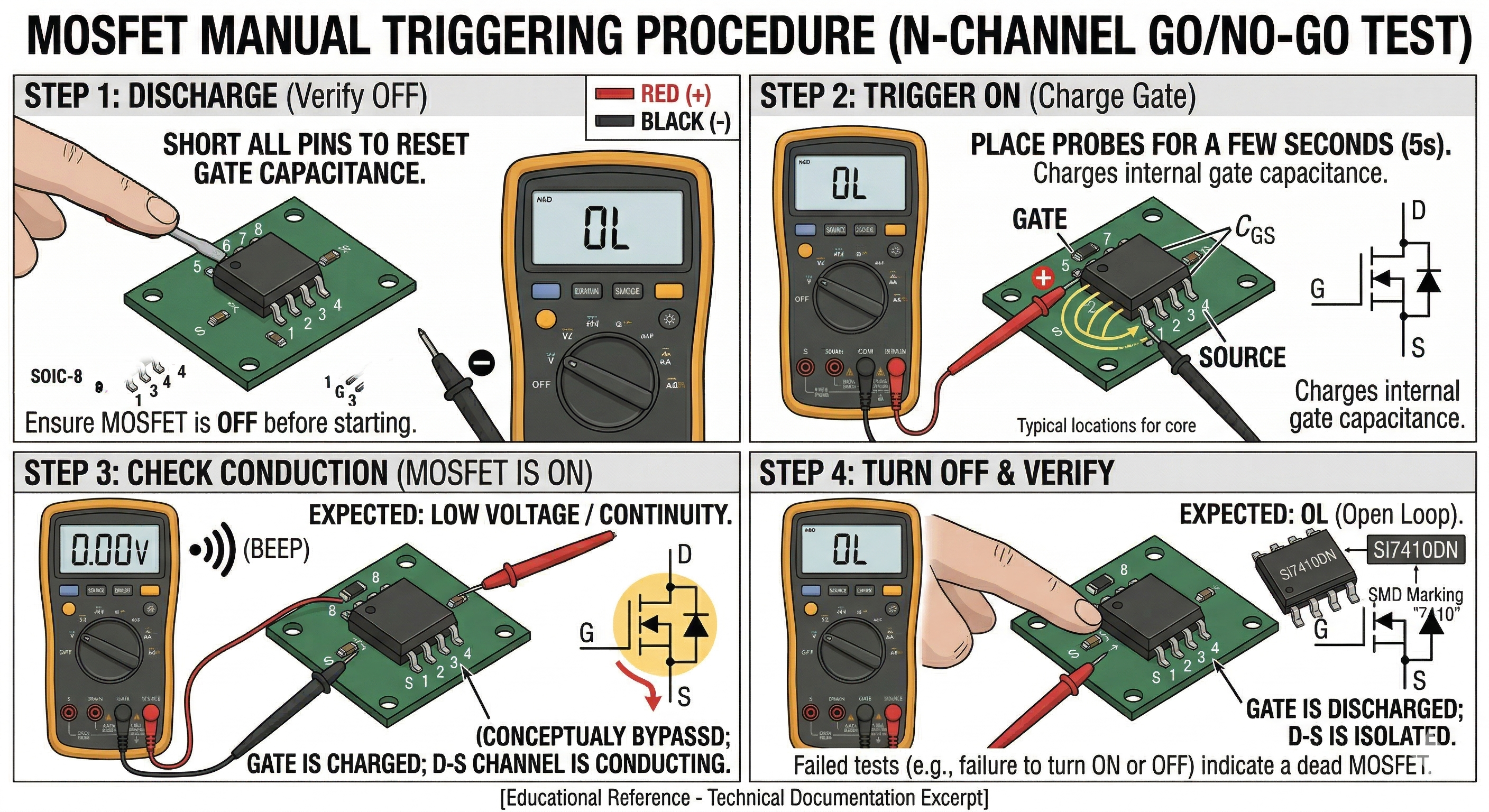
6. The “Switching” (Go/No-Go) Test
You can use your multimeter’s internal battery in Diode Mode to verify if the MOSFET can actually trigger “ON” and “OFF.”
The Trigger Process (N-Channel Example):
- Discharge: Short all pins to ensure the MOSFET is OFF.
- Turn ON: Place the Red (+) probe on the Gate and the Black (-) probe on the Source for a few seconds. This “charges” the gate capacitance.
- Check Conduction: Move the Red (+) probe to the Drain (keeping Black on the Source).
- Expected Reading: You should see a very low voltage drop (close to 0V) or a continuity beep, indicating the MOSFET is now “ON.”
- Turn OFF: Touch the Gate and Source together with your finger or a probe. Re-test Drain to Source.
- Expected Reading: It should return to OL (Open Loop).
7. In-Circuit vs. Out-of-Circuit Nuances
Diagnostics performed while the MOSFET is soldered to a laptop motherboard can be deceptive:
- Parallel Paths: A “short” reading between Drain and Source might actually be a shorted decoupling capacitor nearby.
- Low Resistance Rails: On modern GPUs or CPUs, the resistance to ground on the output side of a MOSFET is naturally very low (often $1\Omega$ to $5\Omega$). Do not mistake this for a failed MOSFET.
- The “Isolation” Rule: If you measure a short ($0\Omega$) in-circuit, remove the MOSFET and test it again on your bench to confirm the component itself is the culprit.
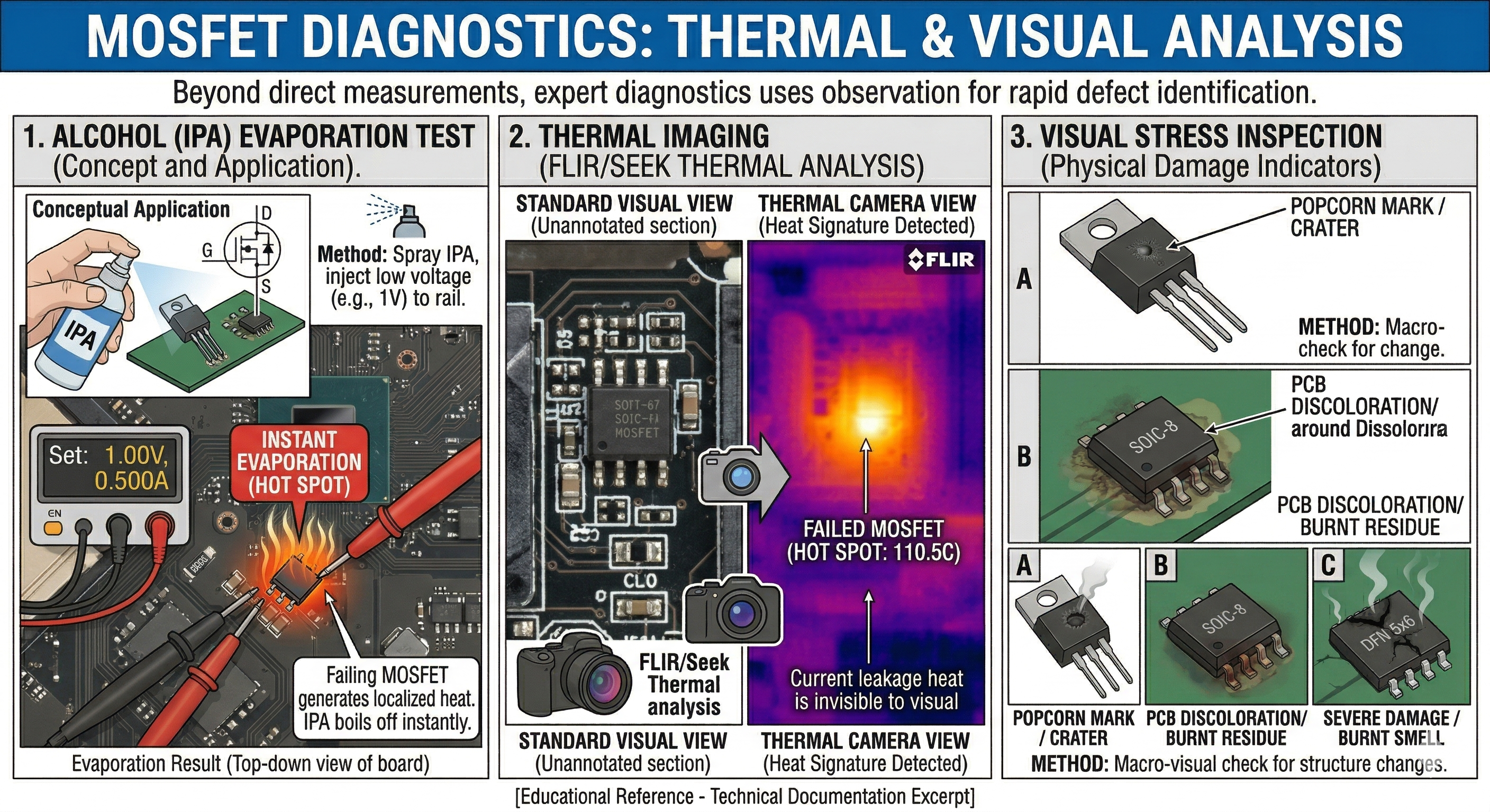
8. Thermal and Visual Analysis
Often, electronics repair involves “looking” as much as “measuring.”
- The Alcohol/Rosin Test: If you suspect a MOSFET is shorted but can’t find it, inject a low voltage (e.g., 1V) into the shorted rail. Sprayed Isopropyl Alcohol (IPA) will evaporate instantly off a failing MOSFET as it generates heat.
- Thermal Imaging: Using a FLIR or Seek Thermal camera will show a “Hot Spot” where the MOSFET is leaking current to ground.
- Visual Stress: Look for “popcorn” marks (tiny craters), discoloration of the PCB around the pins, or a “burnt” smell.
9. Gate Drive Circuitry Check
If a MOSFET is found to be shorted (especially Drain-to-Gate), it often sends high voltage back into the PWM Controller or the Gate Resistor.
- Always measure the resistance of the Gate Resistor (usually a small 1$\Omega$ to 47$\Omega$ SMD resistor). If it is open-circuit or high resistance, the new MOSFET will not trigger.
- Formula for Gate-to-Source Voltage: \(V_{GS} = V_{Gate} - V_{Source}\)
- For an N-Channel MOSFET to turn on, $V_{GS}$ must typically be $> 4.5V$ (Logic Level) or higher than the threshold voltage $V_{th}$ specified in the datasheet.
10. Inductor/Phase Testing
In laptop VRMs (Voltage Regulator Modules), MOSFETs work in pairs (High-side and Low-side).
- If the High-side MOSFET shorts, it may send the full 19V charger voltage directly to the CPU/GPU, likely destroying it.
- Always check the resistance from the Inductor (Coil) to the 19V main rail. It should be $OL$. If it’s $0\Omega$, the High-side MOSFET is dead.
MOSFET Identification and Equivalent Replacement Guide
When a MOSFET is confirmed dead, identifying the correct part or a suitable alternative is critical for a successful repair.
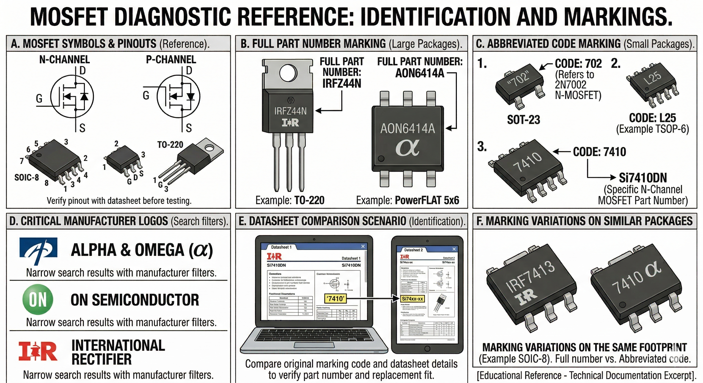
11. Identifying the Part Number
The part number is usually laser-etched on the top of the component. However, space constraints on small packages often lead manufacturers to use shorthand “SMD Codes.”
A. Common Identification Scenarios
- Full Part Numbers: Larger MOSFETs (like PowerFLAT 5x6 or TO-220) often list the full number.
- Example: AON6414A -> Alpha & Omega N-Channel MOSFET.
- Abbreviated Codes: Smaller chips (SOT-23, TSOP-6) use 2-4 character codes.
- Example: A marking of “7410” on a SOIC-8 package often refers to the Si7410DN.
- Manufacturer Logos: Look for logos like the “$\alpha$” (Alpha & Omega), “ON” (ON Semiconductor), or “IR” (International Rectifier) to narrow down the manufacturer before searching.
12. Using Datasheets to Find Replacements
If the exact part is unavailable, you can substitute it with an “Equivalent” or “Better” MOSFET by comparing these five critical parameters in the datasheet:
1. Polarity (The Dealbreaker)
You cannot swap an N-Channel for a P-Channel. Ensure the replacement is the same type.
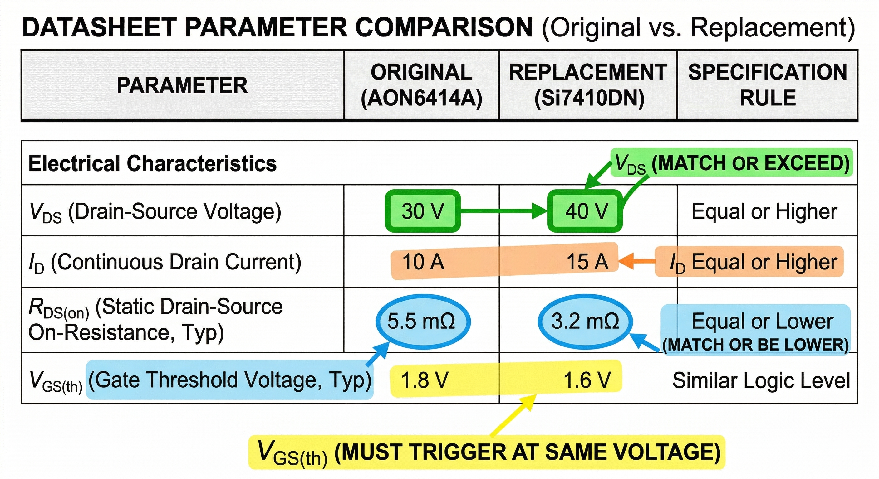
2. $V_{DS}$ (Drain-Source Voltage)
This is the maximum voltage the MOSFET can handle when OFF.
- Rule: The replacement must be Equal or Higher.
- Example: If the original is 30V, a 40V replacement is fine, but a 20V replacement will fail.
3. $I_D$ (Continuous Drain Current)
The maximum current the MOSFET can handle.
- Rule: The replacement must be Equal or Higher.
- Example: If the original is 10A, use a 10A or 15A replacement.
4. $R_{DS(on)}$ (Static Drain-Source On-Resistance)
The resistance of the MOSFET when it is fully turned on. Lower resistance means less heat generated.
- Rule: The replacement must be Equal or Lower.
- Example: If the original is 5m$\Omega$, a replacement with 4m$\Omega$ is an upgrade; 10m$\Omega$ may overheat and fail.
5. $V_{GS(th)}$ (Gate Threshold Voltage)
The voltage required at the Gate to start turning the MOSFET on.
- Rule: The replacement must be Similar. If the original triggers at 1V-2V (Logic Level), a replacement requiring 4V-6V will never turn on in that circuit.
13. Package and Footprint Compatibility
Even if the specs match, the physical package must fit the PCB pads. Common laptop packages include:
- SOIC-8: Standard 8-pin leaded package.
- PowerFLAT / DFN 5x6: Bottom-terminated pad (common in modern high-current 19V rails).
- SOT-23: Tiny 3-pin package for signal switching.
Pro Tip: When substituting, also check the Total Gate Charge ($Q_g$). If the $Q_g$ is significantly higher on the replacement, the original PWM controller might struggle to switch it fast enough, leading to “switching losses” and excessive heat.
14. Search Resources
- S-Manuals / Code.info: For looking up 2-3 digit SMD marking codes.
- Mouser / DigiKey / Arrow: Use their parametric search filters to input your original specs ($V_{DS}$, $I_D$, etc.) and find currently stocked alternatives.
- AllDataSheet / DatasheetCatalog: To pull the original PDF for comparison.